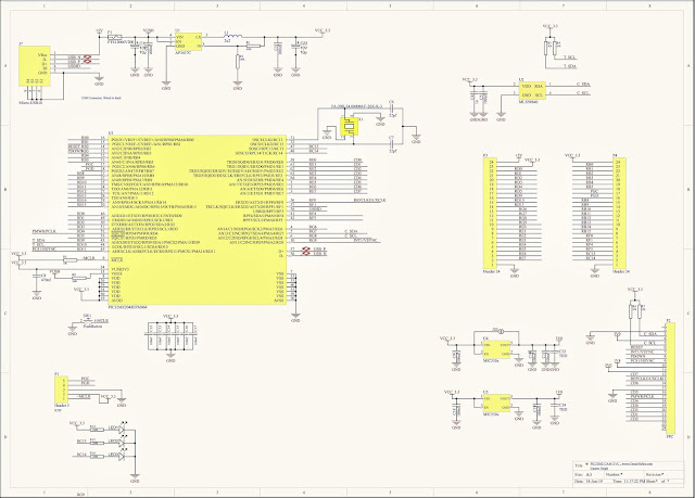

In addition to this, circuit also consists of four more pins. For the formation of an oscillator, we are provided with two pins XTAL1 and XTAL2 which are used for connecting a resonant network in 8051 microcontroller device. During each clock pulse a particular operation will be carried out, thereby, assuring synchronization among operations. Synchronization among internal operations can be achieved with the help of clock circuits which are responsible for generating clock pulses. Register A also involved in data transfers between the microcontroller and external memory.Ĩ051 microcontroller also has 7 Special Function Registers (SFRs). Register B is usually unused and comes into picture only when multiplication and division functions are carried out by Register A. The operations of addition, subtraction, multiplication and division are carried out by Register A. These registers are used to store the output of mathematical and logical instructions. Register A serves as an accumulator while Register B functions as a general purpose register. 8051 microcontroller has 2 registers, namely Register A and Register B. Registers are usually known as data storage devices.
#INT1 TASK3 PC#
This way the PC increments automatically, holding the address of the next instruction.

The PC holds the address of the next instruction residing in memory and when a command is encountered, it produces that instruction. The basic function of program counter is to fetch from memory the address of the next instruction to be executed. Logical AND, OR and exclusive OR (XOR) come under logical operations.Ī program counter is a 16-bit register and it has no internal address. Interrupt control logic with five sources of interruptĪll arithmetic and logical functions are carried out by the ALU.Īddition, subtraction with carry, and multiplication come under arithmetic operations. Four general purpose parallel input/output portsħ. Let us see the major components of 8051 microcontroller and their functions.Īn 8051 microcontroller has the following 12 major components:Ħ. The 8051 microcontroller is an 8-bit microcontroller.

Pin 40 − This pin is used to provide power supply to the circuit. Lower order address and data bus signals are multiplexed using this port. Pins 32 to 39 − These pins are known as Port 0.

It is used to demultiplex the address-data signal of port. Pin 31 − This is ALE pin which stands for Address Latch Enable. It is used to enable/disable the external memory interfacing. Pin 30 − This is EA pin which stands for External Access input. It is used to read a signal from the external program memory. Pin 29 − This is PSEN pin which stands for Program Store Enable. Higher order address bus signals are also multiplexed using this port. Pins 21 to 28 − These pins are known as Port 2. Pin 20 − This pin provides the power supply to the circuit. Pins 18 & 19 − These pins are used for interfacing an external crystal to get the system clock.
#INT1 TASK3 SERIAL#
This port serves some functions like interrupts, timer input, control signals, serial communication signals RxD and TxD, etc. Pins 10 to 17 − These pins are known as Port 3. Pin 9 − It is a RESET pin, which is used to reset the microcontroller to its initial values. It is internally pulled up, bi-directional I/O port. This port doesn’t serve any other functions. Pins 1 to 8 − These pins are known as Port 1. The pin diagram of 8051 microcontroller looks as follows − Comparison of Microprocessor and Microcontroller - Block diagram of Microcontroller –Functions of each block - Pin details of 8051 – ALU –ROM– RAM – Memory Organization of 8051 - Special function registers –Program Counter – PSW register – Stack - I/O Ports – Timer – Interrupt – Serial Port – Oscillator and Clock - Clock Cycle – State - Machine Cycle –Instruction cycle – Reset – Power on Reset – Overview of 8051 family


 0 kommentar(er)
